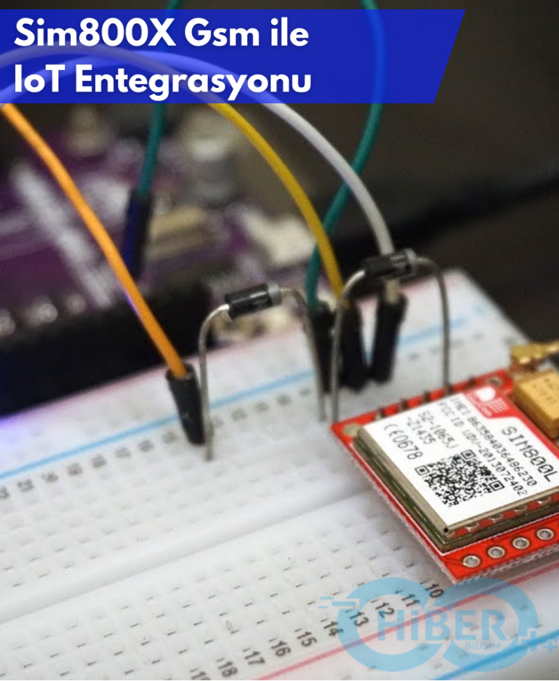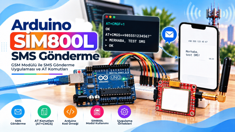
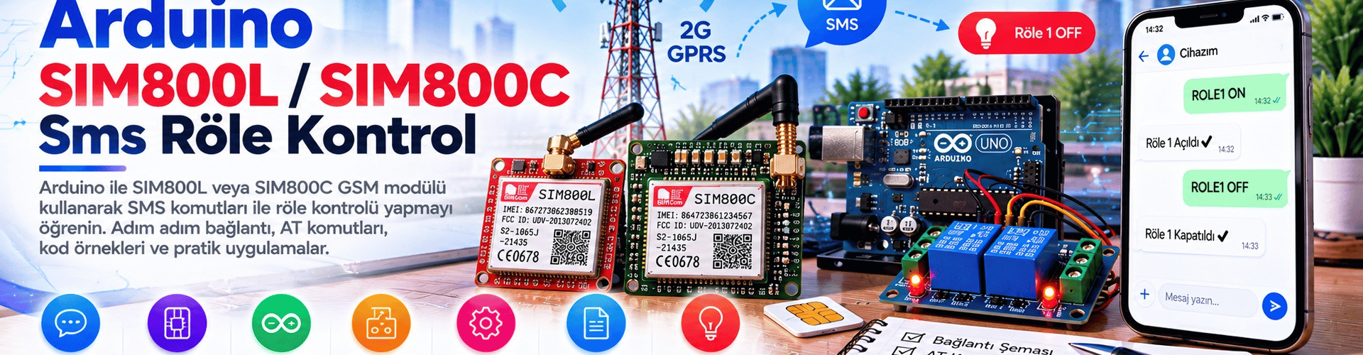
Building an SMS-controlled relay with a small microcontroller board is very easy. In this article, we use the SIM800L/SIM800C GSM module and Arduino Uno to develop a single-channel SMS relay. The relay is controlled via ON/OFF commands sent from the messaging app on your phone.
Hardware and Power Supply
This circuit needs a stable and clean 3.7–4.2V/2A (min) DC power supply for proper performance. Although most SIM800L modules work at 3.7V, some may not operate below 4V due to the components used. Component quality can vary between module manufacturers. Therefore, use an LM2596 to power the module at a maximum of 4.2V. However, do not use the LM2596 module permanently in a finished project; the LM2596 provides convenience for prototyping.
SIM Card and Network Registration
Before powering on the system, remember to insert a valid micro SIM card into the holder. Usually, the SIM card automatically registers to the home network within a few seconds. The built-in LED indicator on the SIM800L module blinks once every two to three seconds (not continuously) when fully registered to the network.
SMS Commands
Let's start by sending an SMS: sending the text “ON” (not case-sensitive) turns the relay on, and “OFF” turns it off. The relay contacts can be connected as desired to switch any suitable electrical load.
Arduino Code
The Arduino code is a basic sketch that does not require a special SIM800L library. It works with AT commands, so no library is needed. In the code, RX and TX pins are assigned as software serial pins; this deliberately keeps the Arduino hardware serial port available for the serial monitor.
/*
 * SIM800L SMS RELAY v1.0
 * Arduino Hardware (Author): (ATmega328)
 * Arduino IDE (Author): 1.6.9
 */

#include
SoftwareSerial mySerial(10,11); // (Rx,Tx > Tx,Rx)

char incomingByte;
String inputString;
int relay = 13; // röle pini

void setup()
{
 pinMode(relay, OUTPUT);
 digitalWrite(relay, LOW); // Röle açılışta kapıyoruz
 Serial.begin(9600);
 mySerial.begin(9600);

 while(!mySerial.available()){
 mySerial.println("AT");
 delay(1000);
 Serial.println("Connecting...");
 }
 Serial.println("Connected!");
 mySerial.println("AT+CMGF=1"); //Set SMS modu
 delay(1000);
 mySerial.println("AT+CNMI=1,2,0,0,0");
 delay(1000);
 mySerial.println("AT+CMGL=\"REC UNREAD\"");
 }

void loop()
{
 if(mySerial.available()){
 delay(100);

 // Serial Buffer
 while(mySerial.available()){
 incomingByte = mySerial.read();
 inputString += incomingByte;
 }

 delay(10);

 Serial.println(inputString);
 inputString.toUpperCase();

 //turn RELAY ON or OFF
 if (inputString.indexOf("ON") > -1){
 digitalWrite(relay, HIGH);
 }
 if (inputString.indexOf("OFF") > -1){
 digitalWrite(relay, LOW);
 }

 delay(50);

 //Delete Messages & Save Memory
 if (inputString.indexOf("OK") == -1){
 mySerial.println("AT+CMGDA=\"DEL ALL\"");

 delay(1000);}

 inputString = "";
 }
}
After uploading the code, take some time to ensure the hardware setup is correct.
Troubleshooting
If the power supply is insufficient, the module may shut down or reset during operation. In case of a fault, try power cycling the system. Ensure the network registration succeeds again, and only then perform a hardware reset using the reset button if necessary.
The provided code is for prototyping purposes; it is meant to give an idea, and you can develop it further in your own projects.