Portable power is everywhere, but building your own power bank circuit is a different level of electronics learning. You can create a rechargeable USB power source with lithium cells, a protection circuit, and a voltage converter while controlling capacity, size, and output. In this technical guide, Hiber Bilişim in Adana explains two practical approaches: a ready-made dual USB LiPo charging module with display, and a custom build using a 3S BMS plus a step-up 5V module. Both routes can work, but they require careful wiring, correct polarity, and respect for lithium battery safety.
Core Blocks of a Power Bank Circuit
A standard power bank circuit contains four functional blocks. Energy storage is typically a Li-ion 18650 cell or a LiPo pouch. Charge management controls input current and voltage so the cell charges safely. Protection prevents overcharge, overdischarge, overcurrent, and short circuits. Voltage conversion delivers a stable 5V USB output from the cell voltage. In a ready-made module, these blocks are integrated. In a DIY design, you connect separate boards and must understand how they interact.
Ready-Made Module: Dual USB Output with Display
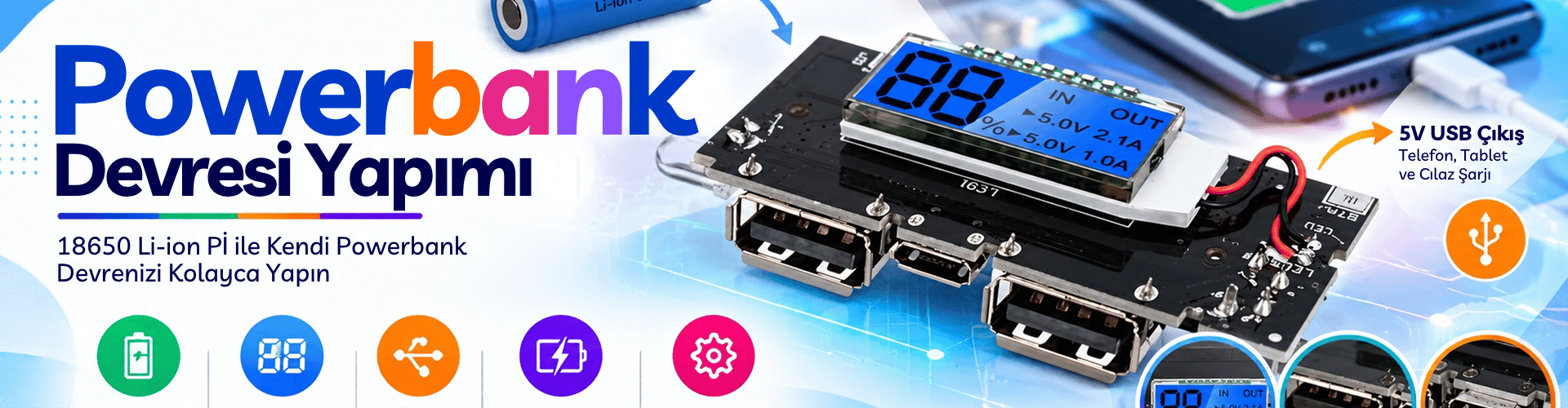
The fastest method is to use a module such as the Powerbank Dual USB Output, Display - LiPo Charger Circuit available from Hiber Bilişim. It combines charging, protection, boost conversion, and display functions on one board. This reduces wiring errors and is safer for first-time builders.
Why This Module Simplifies Your Build
Because the charge controller and 5V output converter are already integrated, you mainly connect the battery terminals. The module manages constant-current/constant-voltage charging, output regulation, and low-voltage cutoff. The display gives a quick battery status, so you do not need an external voltmeter during normal use.
Wiring Basics for the Ready Module
Connect the positive cell terminal to B+ and the negative terminal to B− exactly as marked. Keep wires short and use an adequate wire gauge to reduce voltage drop. After soldering, check for solder bridges and accidental shorts. Connect a charged cell, confirm the display turns on, and measure the USB output with a multimeter before plugging in a phone.
DIY Power Bank Circuit with 3S BMS and Boost Step-Up Module
Builders who want a modular system can use a separate 3S BMS and a voltage converter. A 3S BMS manages three lithium cells connected in series, producing a nominal voltage around 11.1V. The boost step-up 5V module is designed to raise a single lithium cell voltage from about 3.7V to 5V. Therefore, you must match the converter to your battery configuration: use a boost module for a 1S cell, or a buck converter for a 3S pack if you want a 5V USB output.
The Role of the 3S BMS
The 3S BMS protects the series pack by monitoring each cell. It typically prevents overcharge above about 4.25V per cell, overdischarge below about 2.8V per cell, and short-circuit current. Balance leads help equalize cell voltages. Wire order matters: connect main negative, first balance point, second balance point, and main positive according to the module label. After wiring, measure the total pack voltage at the BMS output before connecting the converter.
Boost Step-Up 5V Module and USB Output
For a single-cell build, connect the boost module input to the protected cell or BMS output. It raises the input voltage to a stable 5V for USB charging. Use a USB female connector and ensure the data lines are configured as required by your devices. For a 3S pack, a buck step-down module is the correct choice to convert the higher pack voltage down to 5V. Always test the output voltage before connecting a load.
Step-by-Step Wiring Sequence and Safety Checks
Regardless of the method, follow a logical assembly order. First select cells with similar capacity, voltage, and internal resistance. Second, connect balance leads and main power cables to the BMS. Third, confirm the BMS output voltage with a multimeter. Fourth, connect the converter module and optional power switch. Finally, solder the USB output and insulate all exposed connections.
Recommended Connection Order
Start with the battery, then protection, then converter, then output. Never solder the USB connector to the converter while the battery is connected. Use a fused or protected path if possible. Double-check polarity before every permanent solder joint.
Insulation and Thermal Considerations
Lithium cells can deliver high current during a short circuit, so cover bare terminals with Kapton tape or heat shrink. Use an enclosure that allows some ventilation. Do not charge unattended, and stop using any pack that becomes unusually hot, swollen, or drops below safe voltage.
Battery Selection and Capacity Planning
Capacity in milliampere-hours depends on how many cells you use and how they are connected. Parallel connections increase capacity while keeping voltage the same; series connections increase voltage but not capacity. A single 18650 cell with a nominal 3.7V and 2500mAh stores roughly 9.25Wh. After boost conversion to 5V, delivered capacity is lower due to conversion losses, often in the range of 85–90 percent efficiency depending on the module. Always check the manufacturer datasheet for charge and discharge limits.
Common Mistakes and Troubleshooting
The most common mistakes are reverse polarity, mismatched cells, missing protection, and using the wrong converter for the pack voltage. If the output is zero, check the BMS output first; some BMS boards need a brief charge or load to wake up. If the voltage is unstable, verify that the input voltage stays within the converter operating range and that the load current does not exceed the module rating. If a cell gets warm during testing, disconnect immediately and inspect wiring.
Building a power bank circuit is a hands-on way to understand battery management and DC-DC conversion. The ready dual USB module is ideal for a compact, reliable build, while a separate 3S BMS and converter offer more flexibility for learning and custom enclosures. In both cases, correct polarity, insulation, and testing are non-negotiable. Hiber Bilişim in Adana can supply the modules and guidance you need for a safer project.
Tell us your battery configuration and output requirements; Hiber Bilişim will help you choose the right power bank circuit components for your next build.