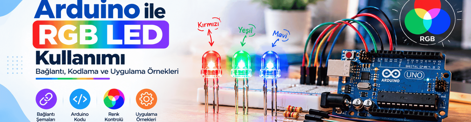
<p>RGB LEDs open the door to nearly endless color possibilities in Arduino projects. For makers in Adana, learning to control an RGB LED with an Arduino Uno is a practical way to understand pulse width modulation (PWM), common anode/cathode wiring, and color mixing. This guide walks through the hardware setup, the differences between LED types, and a corrected Arduino sketch that produces red, green, blue, white, purple, and cyan colors.</p>
Understanding RGB LED Types: Common Anode vs Common Cathode
<p>An RGB LED packages three separate LEDs—red, green, and blue—inside a single housing. The four pins typically include one common connection and three color pins. Depending on how the internal LEDs are connected, the component is either a common anode or common cathode type. This distinction determines both the wiring and the logic level required to turn on a color.</p>
Common Anode RGB LEDs
<p>In a common anode RGB LED, all three anodes are tied to a single external pin. To light a color, you connect the common anode to a positive supply, such as 5V on an Arduino Uno, and pull the corresponding color pin LOW through a current-limiting resistor. In code, an analogWrite value of 0 produces full brightness, while 255 turns the LED off.</p>
Common Cathode RGB LEDs
<p>In a common cathode package, all three cathodes share one pin. Connect the common cathode to GND and drive the red, green, or blue pins HIGH through resistors. With this type, an analogWrite value of 255 gives maximum brightness and 0 turns the LED off.</p>
Identifying Your RGB LED Type
<p>If the longest pin is common, a common cathode LED usually has the longest lead as the common cathode, while a common anode also has a common pin but may be identified in the datasheet. You can test with a 3V coin cell and a resistor: apply positive to one color pin and negative to the common pin. If the color lights with common negative, it is common cathode; if it lights with common positive, it is common anode.</p>
PWM and Arduino Pins: The Key to Smooth Color Mixing
<p>Pulse width modulation (PWM) lets a digital pin produce an average voltage that varies with duty cycle. On the Arduino Uno, only certain pins support output PWM: 3, 5, 6, 9, 10, and 11. The original sketch assigned blue to pin 7, which is not a PWM-capable pin, so analogWrite would not produce the intended analog output. For smooth color mixing, always route RGB channels to PWM pins.</p>
Why Duty Cycle Matters
<p>The duty cycle is the percentage of time a signal is HIGH during one period. A 0% duty cycle is always off, 50% is half brightness, and 100% is full brightness. Arduino's analogWrite function accepts values from 0 to 255, mapping them to the PWM duty cycle on supported pins. Because the switching frequency is usually high enough, your eye perceives the average brightness rather than flicker.</p>
Wiring Your RGB LED with Arduino in Adana
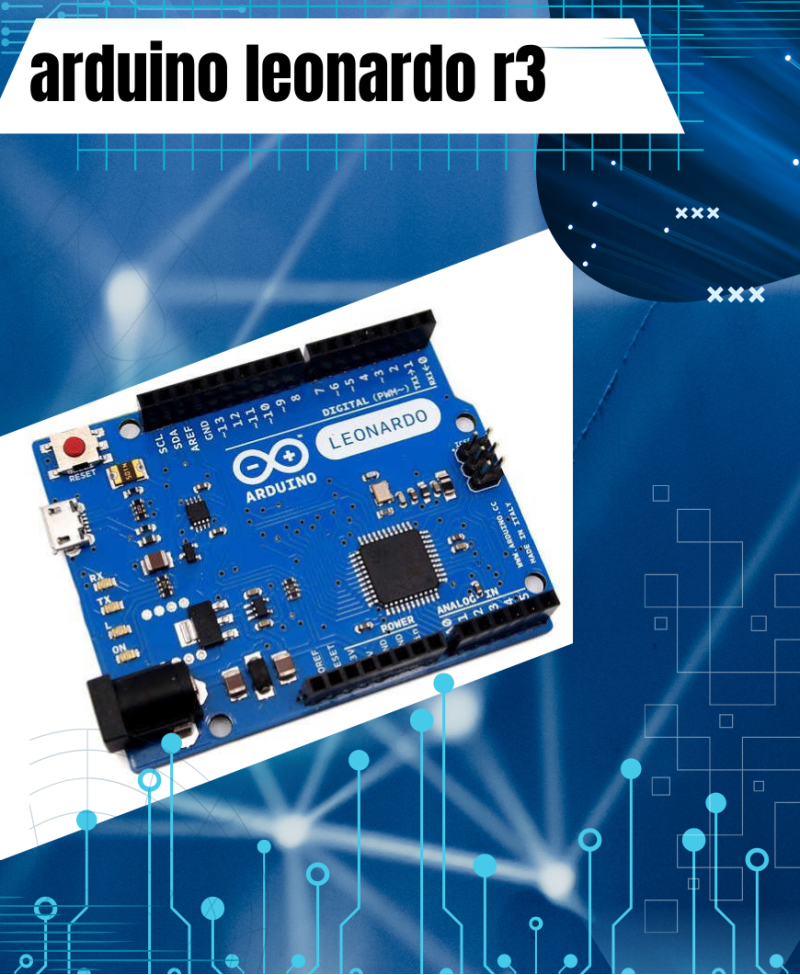
<p>You can find the required components at electronics shops in Adana or through online suppliers. For this project you need an Arduino Uno, one common cathode or common anode RGB LED, three 220-ohm resistors, a breadboard, and jumper wires.</p><p>For a common cathode LED, connect the common pin to GND. Connect the red pin to digital pin 9 through a 220-ohm resistor, green to pin 10 through a resistor, and blue to pin 11 through a resistor. For a common anode LED, connect the common pin to 5V and keep the same resistor connections; the sketch must invert the PWM values.</p>
Improved Arduino Sketch for RGB LED Control
The following corrected sketch uses PWM-capable pins, constant pin definitions, and clear comments. It also changes the ambiguous light blue color to cyan with the RGB value (0, 255, 255).
// Arduino RGB LED Control - Common Cathode
// Author: Berat KURTGÖZ
// Pins: Use PWM-capable pins on Arduino Uno (9, 10, 11)

const int redPin = 9;
const int greenPin = 10;
const int bluePin = 11;

void setup() {
  pinMode(redPin, OUTPUT);
  pinMode(greenPin, OUTPUT);
  pinMode(bluePin, OUTPUT);
}

void loop() {
  setColor(255, 0, 0);    // Red
  delay(1000);
  setColor(0, 255, 0);    // Green
  delay(1000);
  setColor(0, 0, 255);    // Blue
  delay(1000);
  setColor(255, 255, 255); // White
  delay(1000);
  setColor(170, 0, 255);  // Purple
  delay(1000);
  setColor(0, 255, 255);  // Cyan
  delay(1000);
}

void setColor(int redValue, int greenValue, int blueValue) {
  analogWrite(redPin, redValue);
  analogWrite(greenPin, greenValue);
  analogWrite(bluePin, blueValue);
}
Code Walkthrough
<p>The setup function configures pins 9, 10, and 11 as outputs. The loop calls setColor with red, green, and blue values, then waits one second. The setColor function writes the three PWM values to the corresponding pins. For a common anode LED, replace the analogWrite lines with analogWrite(redPin, 255 - redValue); and do the same for green and blue.</p>
Adjusting Brightness and Color
<p>Because analogWrite accepts 0 to 255, you can mix millions of possible colors by changing the three values. To avoid excessive current, always use current-limiting resistors, typically around 220 ohms for each color channel on a 5V Arduino.</p>
Troubleshooting and Next Steps
<p>If the LED does not light, check that the common pin is wired correctly and that the resistors are connected in series with each color pin. If colors appear inverted or behave unexpectedly, confirm whether your LED is common anode or common cathode, and adjust the code accordingly. If one channel fails to vary brightness, make sure it is connected to a PWM-capable pin.</p><p>Once the basic color cycle works, try adding potentiometers to control each channel manually, or create smooth color fades with for loops. These experiments will strengthen your understanding of PWM and Arduino outputs.</p>
<p>Controlling an RGB LED with Arduino combines hardware wiring, PWM knowledge, and simple programming. By correcting the pin assignment and understanding common anode versus common cathode behavior, you can produce reliable color output for projects in Adana and beyond. The sketch provided here gives you a solid foundation for more advanced lighting effects and interactive installations.</p>
Gather your components, upload the corrected sketch, and start mixing colors with Arduino in Adana today.